As a level gauge glass manufacturer, I would like to share this with you.
Routine Inspection and Troubleshooting Methods
-
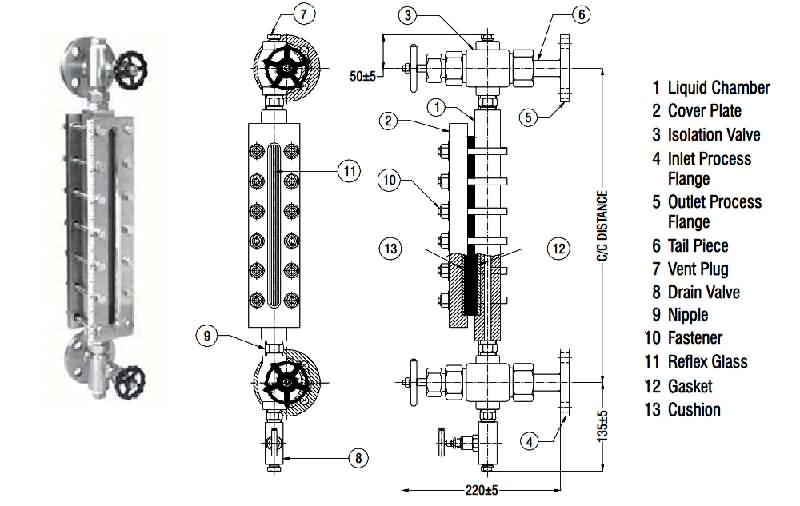
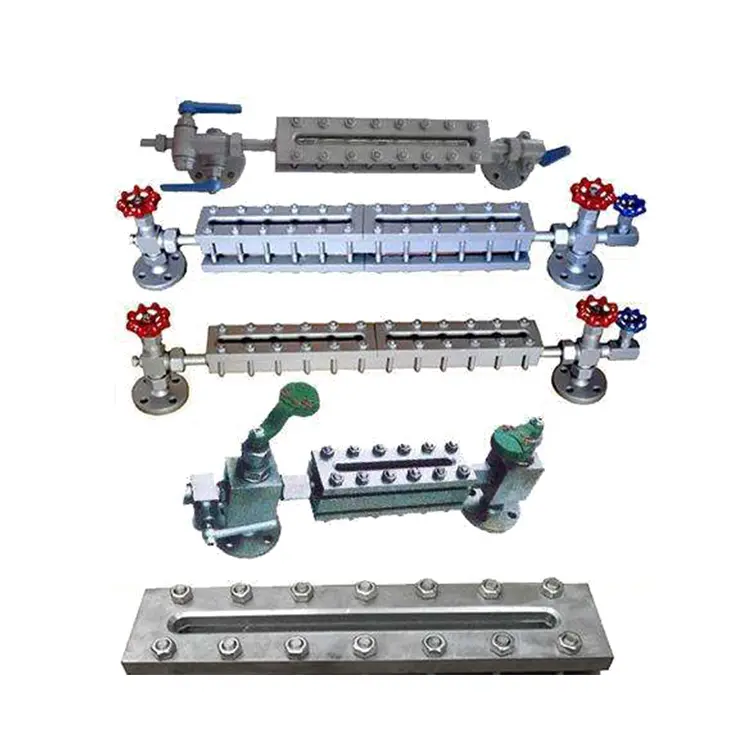
Magnetic Flap Level Gauge
-
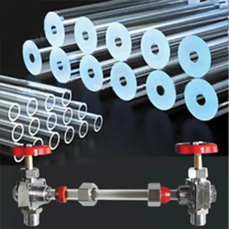
Two-Color Quartz Tube Level Gauge
Use these methods for effective inspection and troubleshooting.
1. First, check if you have connected the power supply correctly. If the connection method is wrong, change it as the operation manual states.
2. Use a three-voltmeter to measure the voltage between +24V and O/P. The voltage should be between 13V and 36V. If the voltage is not normal, check if the circuit or related equipment is faulty.
3. Confirm that the second item is normal. Then, connect a milliamp meter to the 4–20 mA circuit. This will check if the current is normal. If the value is abnormal, replace it with a new product. You can also contact customer service.
4. Use a voltmeter to check the voltage between IN and COM. Normally, it should be about 2.5V. If the voltage is too low, remove the EXC wire to see. If the voltage returns to normal, it means that the magnetic yellow module is abnormal. If the power is still low, it means that something has damaged the signal converter. If you see this problem, replace the signal converter. You can also contact customer service for help.
The float ball drops to the bottom, and the flag board has not returned to zero. The flag board cannot keep up with the falling speed of the float ball. Install a throttling device to slow down the lifting speed of the liquid level.
The flag plate color chip will not turn over, or the disordered color chip exists. Check for any magnetic objects inside or around the body tube. After removing them, sweep the tube with a magnet to ensure the colors are consistent.
Someone turns the color chip 360 degrees. The float’s magnetic field is too strong. Please reach out to customer service for a replacement.
The proximity switch does not work. Check whether the switch is operating normally with an electric meter. When the magnet is close, the contact should be on and the resistance should be less than 300 MΩ. Remove the magnet. The switch will stay open, and the resistance will be over 10 MΩ. If the above requirements are not met, replace it with a new proximity switch.
To connect the signal converter wires to the float continuous level indicator, follow these steps:
-
Identify the wires.
-
Strip the insulation.
-
Connect the wires to the indicator terminals.
-
Secure all connections.
-
Test the setup to ensure proper functioning.
-
Connect the 24V terminal of the signal converter to the +24V terminal of the indicator.
-
Then, connect the O/P of the signal converter to the AI terminal of the indicator.
If it still doesn’t work after powering on, please contact customer service.
Our company’s Transparent Level Gauge is on sale; please contact us.