Introduction
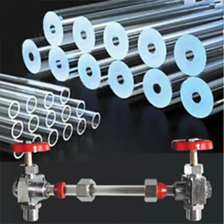
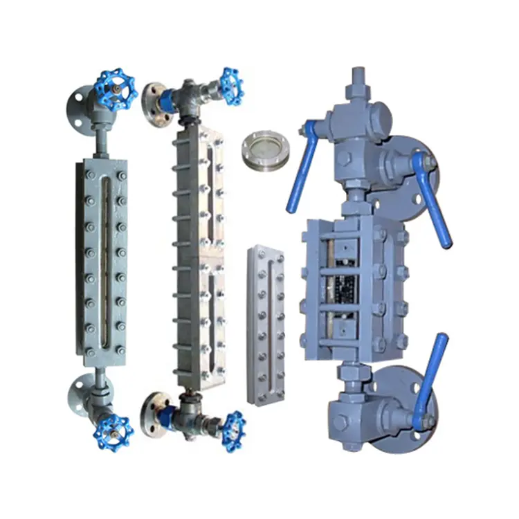
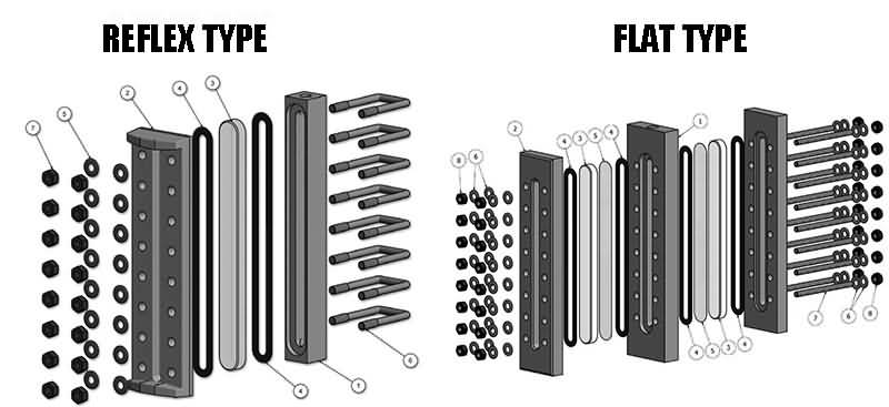
A glass plate (flat) level gauge is a common visual level indicator. It is available in two main glass types: reflex gauge glass and transparent (plain/flat) gauge glass. Correct installation and regular maintenance are essential to protect the glass and ensure safe, reliable operation.
A. Inspection & Disassembly Procedure
Before work: Depressurize and isolate the gauge from the process. Follow site LOTO (lock-out/tag-out) and safety rules.
-
Remove the fastening bolts and nuts.
-
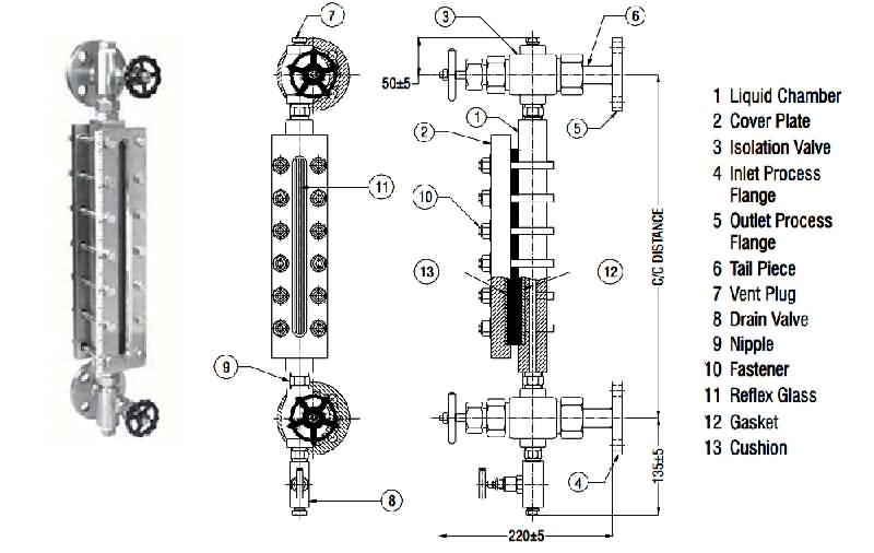
Remove components in this order:
-
gland (pressure plate)
-
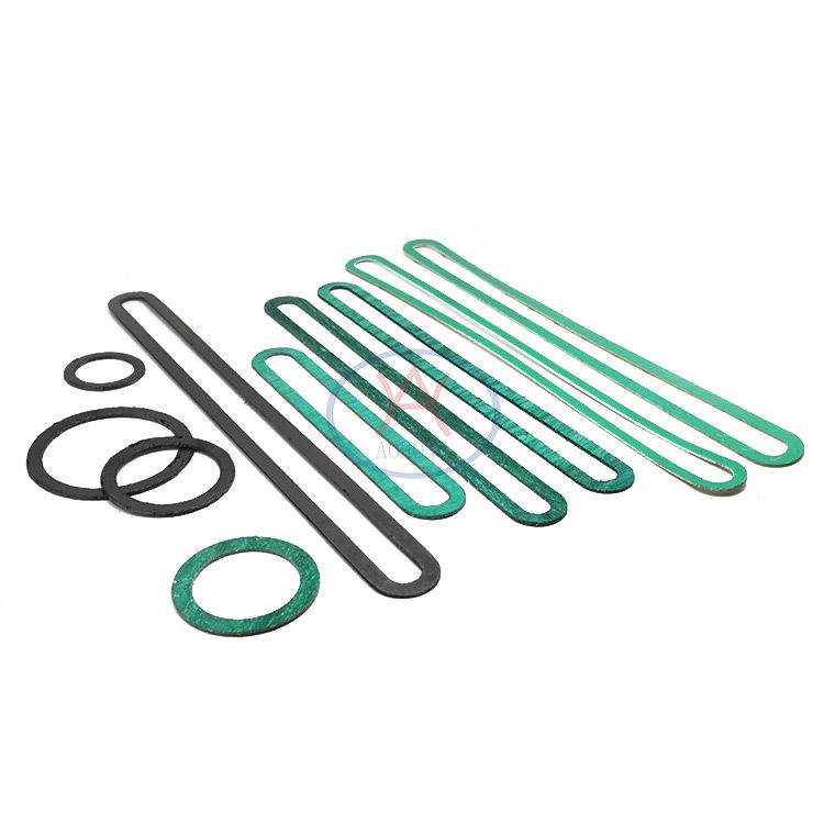
gauge glass gasket
-
gauge glass (reflex or transparent)
-
mica shield (if fitted — mica shields are used only on gauges for alkaline media to protect transparent glass)
-
-
Inspect each part for cracks, corrosion, wear, or deformation.
B. Cleaning & Surface Preparation
-
Clean dust, oil, and loose debris from the gauge housing and parts using appropriate, non-abrasive cleaners.
-
Remove rust from metal surfaces (mechanical or chemical methods as per workshop practice).
-
Remove residual gasket material from the sealing faces; do this carefully to avoid damaging the sealing surface.
-
If required, recondition the sealing face so its surface roughness meets the sealing specification (follow supplier tolerance).
-
Replace all damaged or suspect spare parts with new, approved parts.
C. Reassembly & Installation Sequence
-
Fit a metal graphite gasket to the seating surface.
-
If applicable (alkaline service), place the mica shield in position. (Not used on reflex-type gauges unless specified.)
-
Install the gauge glass (reflex or transparent) in the correct orientation.
-
Fit a second metal graphite gasket and then the gland (pressure plate) or buffer.
-
Fit fastening bolts and nuts loosely to hold the assembly.
Bolt tightening procedure:
-
Tighten the bolts gradually and evenly in a cross pattern (see figure in your product manual).
-
Start with a light initial torque (for example, ~15 N·m) and progressively increase in steps until the final sealing torque is reached.
-
Target final torque: follow the gauge manufacturer’s specification; if unavailable, a final sealing torque around 100 N·m is commonly used on comparable assemblies — confirm with supplier data before applying.
-
Apply torque in several passes (e.g., 20% → 50% → 80% → final) to ensure even compression of the gaskets.
D. Pressure Test (Hydrostatic Test)
-
Perform a hydrostatic pressure test with a test pump at 1.5 × working pressure (or per project/standard requirement).
-
Hold the test pressure and observe for pressure drop for at least 5 minutes. No pressure drop indicates pass.
-
If leaks are detected, isolate, depressurize, and rectify sealing or component issues; replace parts if necessary.
E. Drying & Final Visual Inspection
-
Drain and dry all water from the gauge after the pressure test.
-
Perform a final visual check for correct glass seating, gasket compression, and visible damage.
-
Reconnect the gauge to the process following your plant procedures.
F. Precautions During Installation
-
Inspect all removed bolts for thread damage; replace any with damaged threads.
-
Coat bolt threads lightly with graphite powder or a high-temp lubricant (manufacturer-approved). A mixture of high-temperature grease and machine oil is sometimes used — verify compatibility with gasket and valve materials.
-
Ensure gasket types and thickness match the original specification.
G. Operation & Start-up Recommendations
-
If the gauge or process connection is at an elevated temperature, do not open the isolation valve immediately after fitting; preheat for 20–30 minutes as appropriate so the glass warms gradually and thermal stress is minimized.
-
After initial service, re-tighten pressure plate screws in the cross pattern (1,3,5…2,4,6…) in several passes to maintain even compression.
-
When opening the needle/isolation valve at start-up, open slowly to avoid hydraulic shock and to prevent the steel ball (if present in the valve) from being forced closed by one-way pressure. Once flow stabilizes, the valve may be opened fully. Proper valve operation helps ensure the valve will close automatically in the event of an incident.
H. Alignment & Stress Relief
-
Measure the bolt-hole/ flange parallelism and the distance between the gauge flanges and the vessel flanges before final installation.
-
If flange misalignment or excessive deviation is found, adjust the mating flanges or use appropriate spacers — do not force the gauge into place, as this induces stress that can crack the glass.
I. High-Temperature Service Note
-
For high-temperature media, reduce working pressure and follow supplier guidance. As a practical rule, when process temperatures exceed typical moderate values (example threshold: ~200°C), consult the gauge manufacturer for permitted operating pressures and gasket materials. Always follow the specific product data sheet.
J. Routine Maintenance Recommendations
-
Keep gauge surfaces clean and dry to reduce corrosion risk.
-
Inspect glass and gaskets regularly for scratches, clouding, or chemical attack. Replace glass that shows surface damage affecting visibility or strength.
-
Use only recommended cleaning agents (avoid abrasive pads or HF solutions on silica-containing glass).
-
Maintain a spare-parts kit: gaskets, gland buffer, bolts, and a replacement sight glass matching your gauge specification.

K. Quick Troubleshooting
-
Leak at the glass seam: re-tighten bolts in cross pattern; if leak persists, depressurize and replace gaskets.
-
Clouding or etching of glass: check for chemical attack (e.g., HF); replace glass and review process chemistry compatibility.
-
Cracks after start-up: check for thermal shock or mechanical stress; verify flange alignment and preheat procedure.
Notes & Manufacturer Advice
-
Always follow the exact torque, gasket material and testing procedure specified by the gauge manufacturer or your site engineering standard.
-
Any numerical examples above (initial torque ~15 N·m; final torque ~100 N·m; hydrostatic test 1.5× working pressure; 5-minute hold) are typical industry references — confirm with the product datasheet before application.